|
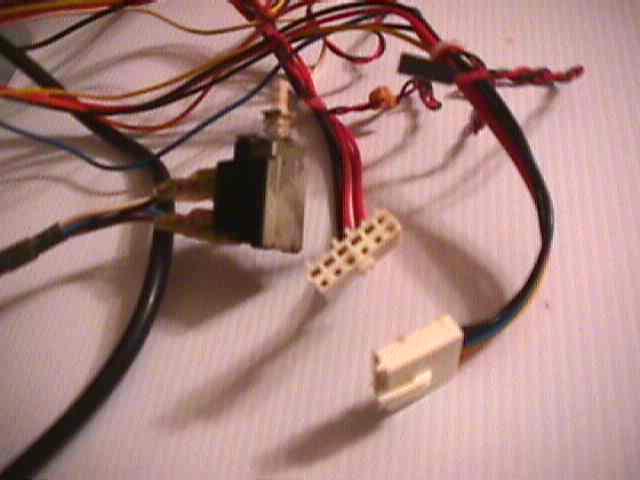
These two white plastic connectors here are what to look for. If you have these two end connectors, you have an
AT power supply.
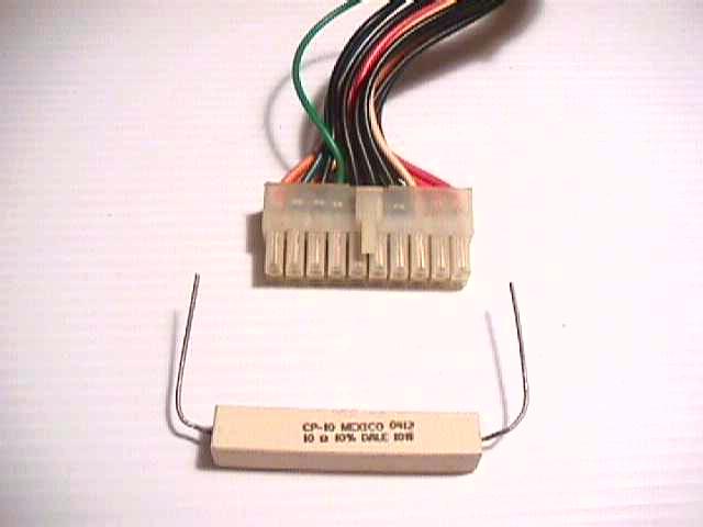
If you have this large 20 pin connector, you have a ATX power supply. Below the connector pictured
is a 10omh 10 watt resistor and is not part of the connector itself.
If you have an ATX power supply, then click here to see what the differences are
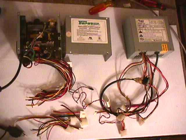
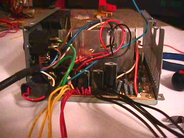
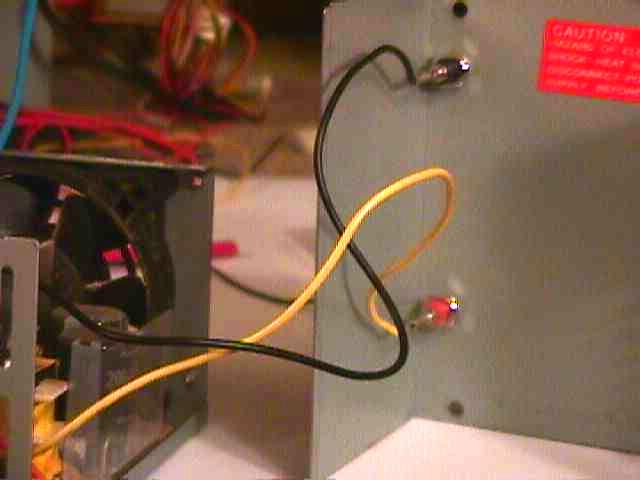
Kind of hard to see here, but the bundle of wires run to a circuit board in the power supply.
You can also see the power button that was mounted to the front of the computer case.
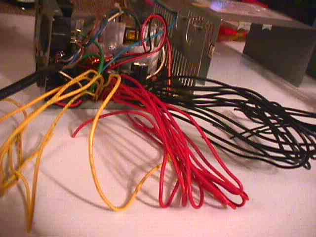
It helps to organize the wires into colors. The Yellow wires are +12 volt, the Red +5 volts,
the Black are ground or common. This should always be checked with
a volt meter for safety, some companies don’t follow this color scheme.
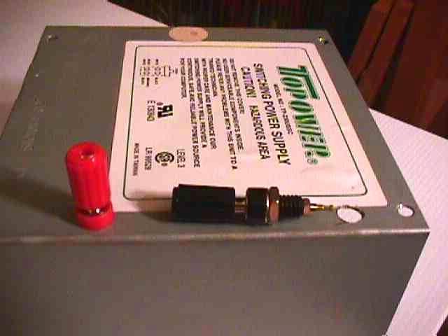
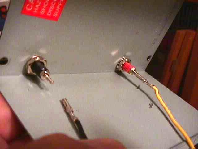
Here is where I drilled the case for the blank banana terminals (Insulated Binding Posts). Make sure you install
the connectors where you have plenty of clearance. You do not want the connectors to touch any of the electronics inside the
power supply.
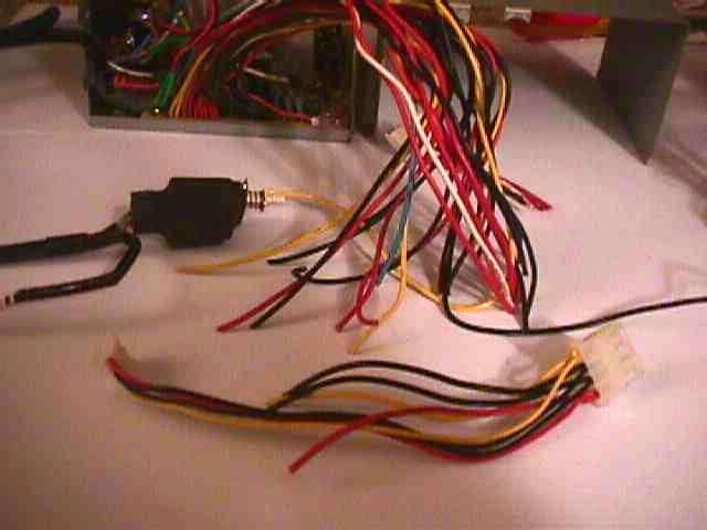
Here I have clipped the extra wires that are not needed. I’ve left four +12 volt yellow
wires, five black (ground) wires and two +5 volt red wires.
Four of the +12 volt Yellow wires will be soldered to the red binding post and four black
wires will be soldered to the black binding post.
One +5 volt Red wire and black wire left over will be connected to a resistor latter on.
One of the red wires will not be used at this time. I'll just tape and tuck it out of
the way for now.
Twist the four yellow wires together and solder them to your positive post.
Next twist the four black wires together and solder them to the negative binding post.
The Red wire is a +5 volt wire. For now I’m just taping the end and tucking it out of the way where it will
not contact anything else. When I get some more connectors I will wire this Red wire up to another red binding post. This
will be used to power my receiver in place of a battery when doing bench testing of different radio gear.
If using to test micro servos (like for small electric’s) do not move the servo arms to there outer most
range or positions. This can break the small plastic gears in the servo gear train. It still works great for powering your
small gear to find centers when installing servo arms. If you don't plan to run your receiver from this power supply, you
can cut the Red wires, also.
Alternative
Below are a few pictures of a different power supply I made for use with my small electric
planes. Since the power requirement is small (less then 1 amp), I’ve saved some soldering time by using just one
yellow and black wire to each post.
I noticed that the ends of the computer wires removed from there plugs, would plug directly
to the banana connector.
Again if you plan to draw more current, then connect 4 yellow wires to the red banana connector and 4
black to the black connector.
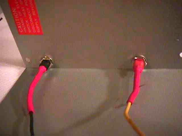
Here you can see I shrink wrapped them for further protection.
Loads and how they effect voltage
Next we need to install one or more resistors to create a load. This load will increase the voltage output as seen
below.
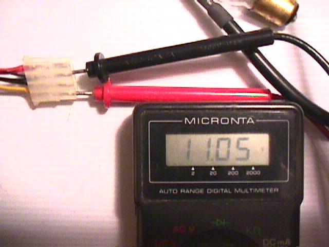
Here is the voltage output with no resistors installed at this time. As you can see it’s only 11.05 Volts.
This is enough volts for the Triton charger which has a voltage operating range from 10.5 volts to just above 13 volts. Some
chargers require a higher voltage or they will not work. Adding resistors will draw more volts from a computer power supply.
See the pictures below for more details.
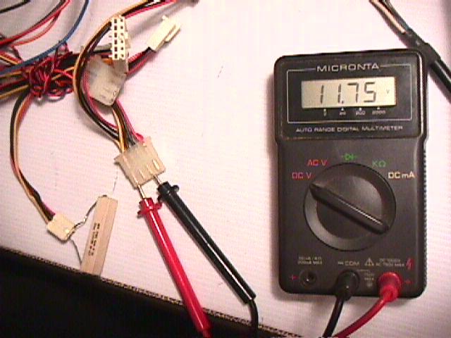
Here is a single 10omh 10watt resistor from radio shack. I placed one lead of the resistor to a +5volt Red wire
and the other resistors lead to a black ground wire. As you can see the voltage output has been raised to 11.75volts.
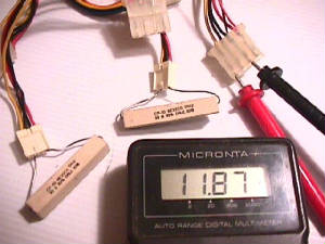
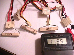
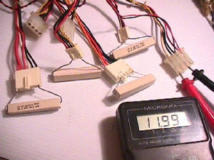
Here are some picture with 2, 3 and then 4 10omh 10watt sandbar resistors and how
they effect voltage output when added.
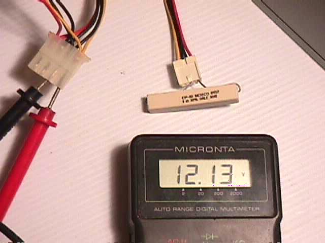
This on the other hand is a single 1ohm 10watt resistor. AS you can see it raises the voltage output to 12.13 volts
all on it’s own.
A few things to consider though is the large amount of heat that comes off this single resistor, also, with the
raise in voltage comes a raise in watt output.
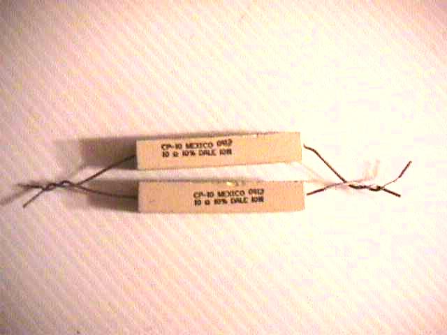
A single resistor may fail from overload, using two resistors in series cuts the load on each preventing damage.
If you wish to try using two 1 Ohm 10 watt resistors, use heat sink compound and attach them to the PS case to help dissipate
the extra heat.
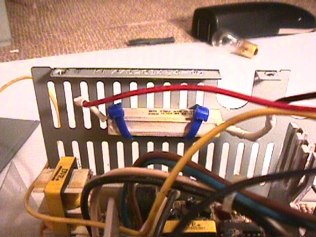
Since 11.75 volts is more then enough for my Triton charger, I will be installing just one 10ohm 10watt resistor.
I connected one +5 volt Red wire and one Black ground wire to the resistor and zip tied it to the case. This will help dissipate
the heat from the resistor as the power supply fan draws air through the circulation vents.
If a higher output voltage is needed to run your charger, just connect two or more (as pictured above)10omh 10watt
resistors together in parallel (or two 1 ohm 10watt resistors in series *not shown* )and
solder to +5 volt Red and Black ground. Use heat shrink to insulate the resistor and power wires from touching the case.
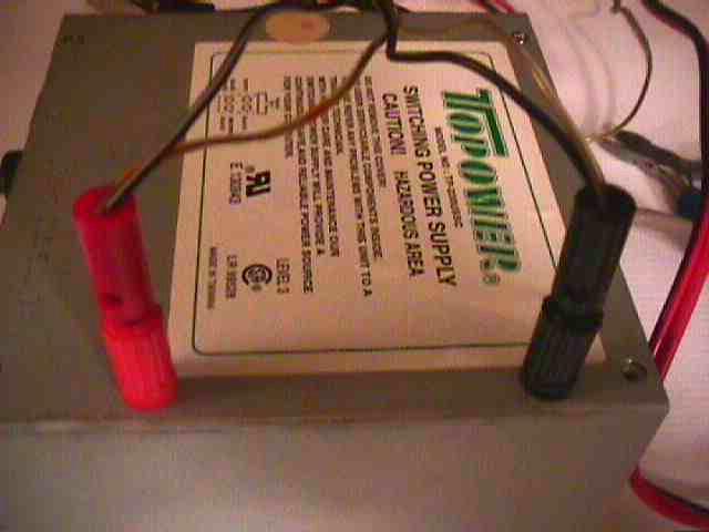
Replace the cover onto the now converted computer power supply making sure the binding posts don't touch the power
supplies internal electronics. You can see I have two banana plugs plugged in from one of my chargers to test it out.
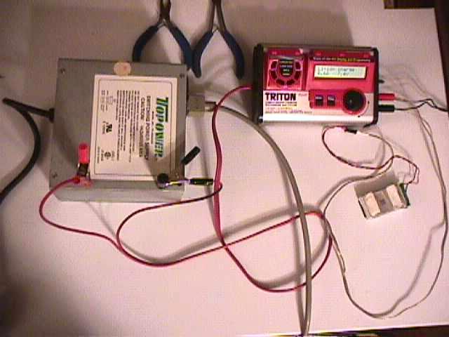
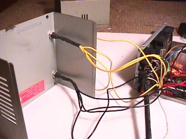
Here is the finished charger powering my Triton charger. The thick black wire on the left is the power cord with
the on/off swich that ran to the front of the computer.
For a cleaner appearance you can buy a toggle swich if you want and mount it to the case and
connect the on/off wires to it.
Notice I’m charging one of the small lipo packs for my small electrics.
This was a fun project. Next I think I will convert a ATX power supply. The conversion
takes a little more work, but isn’t that hard.
|