|
There are a few differences to converting a ATX power supply.
There doesn’t seem to much difference converting a ATX or AT power supply. One you must use a resistor to simulate
the load of different computer components and you must complete a circuit with the PS-ON wire. Follow the same instructions
for the AT power supply conversion except where noted below.
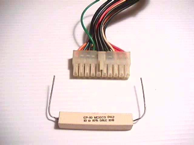
Notice the green wire slightly separated from the wire bundle. This is the power on or PS-ON wire.
Clip the green wire form the connector along with a black wire and twist them together.
If your ATX power supply doesn't come with a rocker on/off power swich on the back, you can also connect
this green wire and a black ground to a toggle swich to turn your power supply on and off.
This green wire would usually run to the mother board of a computer. When turning the computer on the
mother board would complete a circuit with this green wire allowing the power supply to turn on. Since where not using
a mother board this green wire and any of the black ground or common wires must be connected together to complete the circute.
Most ATX power supplies have a safety feature that will not allow them to turn on with out a power
load or power demand of some kind. This usually isn’t a problem since when turning on a computer, the hard drives, floppy
drives ect. startup and place a load on the computers power supply.
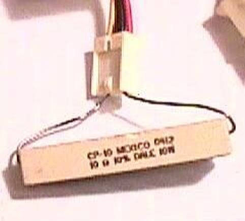
Here I’ve plugged one end of a 10omh 10watt resister into the pin of a +5 volt Red wire and Black ground. Since this
is a used power supply I did this to test if the power supply would power up. Later I will clip the Red and Black wire and
solder them to the resistor.
|
