|
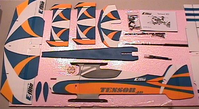
Here is everything laid out that comes with the Tensor 4D. This is one complete kit. It even comes with EZ connectors for
the servo arms. Radio gear, glue and power system are all that is needed.
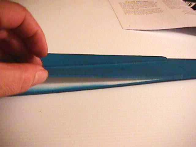
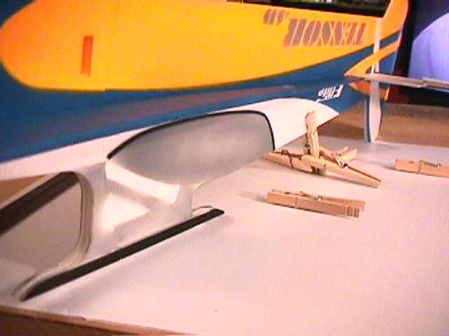
This is one of the horizontal fuselage dubblers that must be removed before the horizontal fuselage cross section can be
installed. The main instruction manual instructs to remove both dubblers, do not do this. There is a Addendum that states
that only one dubbler should be removed. The side that is just tack glued show here. I did this with a new X-Acto Blade.
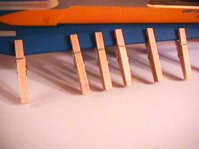
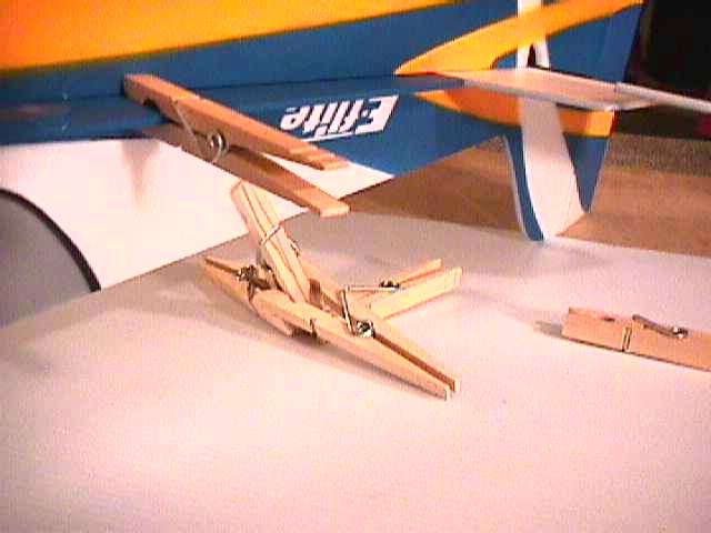
While the glue sets, I found that cloths pins were very helpful holding parts together. The light pressure of the pins
will not cause dents in the foam.
Again the Addendum explains to cut the carbon fibber elevator stiffing joiner to 1 5/8 inch in length. You must do this
or you will not be able to install the elevator control horn.
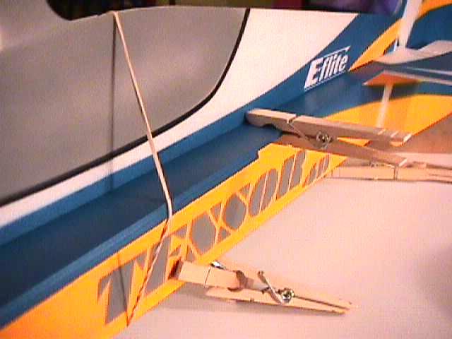
A long thin rubber band helps hold the top and bottom fuselage tight to the horizontal fuse cross section without crushing
the foam.
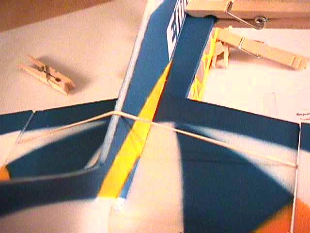
Once the fuselage glue had dried, I slide the rubber band down over the horizontal stab. This held it perfectly in a 90
degree angle while applying the glue and waiting for it to dry.
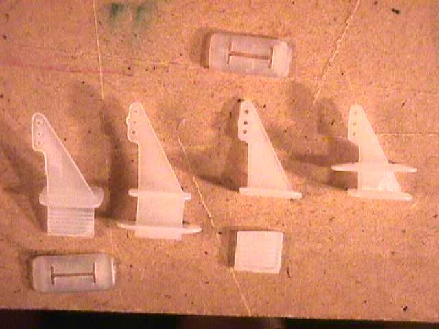
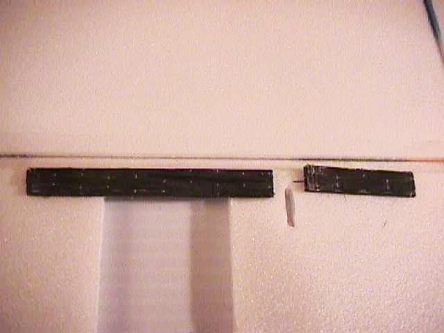
Here is an idea I thought might be worth mentioning. These are small control horns supplied with the kit. Yet the instructions
warn that they are to long to use as is or in there regular manor.
The two control horns on the left are an example of how they would be used normally. Usually the keeper is slipped
on the bottom of the control horn sandwiching the control surface and glued. If you attach them to the control surface this
way, they are two long and will not give enough control throw. Some have installed them this way and drilled a new hole for
the control rod, but this looks unsightly and weakens the control horn. The two horns on the right show an alternative method.
Clip the bottom of the horn off and push the top of the control horn through the bottom of the control surface, then slip
the horn keeper over the top of the horn sandwiching the control surface between the two plates. This shortens the horn with
out weakening it increasing the travel.
|
